As explained on the Saturn Launch Vehicle
Digital Computer (LVDC) page, the LVDC was the digital
computer that guided Apollo's Saturn rockets, while other types of
computers (principally the Apollo Guidance Computer, or AGC for
short) guided the Command Module and Lunar Module. An
extensive collection of AGC software survives, for many of the
Apollo missions. However, only a tiny amount of LVDC
software has become available to us: namely, one
LVDC flight program for a proposed but unflown mission known as
AS206-RAM. But also, we have the software for something
called the PTC ADAPT Self-Test Program ... which for brevity we
refer to as the PAST program. The PAST program is the focus
of this particular page.
The Programmable Test Controller (PTC) was test equipment which
contained a slightly-modified LVDC CPU and whose purpose was to
test the CPU design as well as to provide debugging capabilities
for the software. The PAST program itself, meanwhile, was
software that ran on the PTC and consisted primarily of such test
procedures. Thus while from the viewpoint of the Apollo era
the PTC's CPU was not precisely an LVDC CPU, and the PAST program
was not precisely LVDC software, from a viewpoint 55 years later
(when I'm writing this), it's much more convenient to think of the
PTC is as being an LVDC and the PAST program as being LVDC
software.
The reason this is significant is that while the Virtual AGC
Project is excited to be able to provide LVDC software publicly
(to the extent that the U.S. regulatory environment allows us to
do so), the main purpose is to provide working software emulations
of the original Apollo-era flight computers, including the LVDC,
which are capable of accurately running that original flight
software. The existence of the original PAST program — even
more so that the existence of the original flight programs —
advances this goal by helping us to validate the software
emulation of the CPU. That's because successfully running a
test program in the emulator gives us much more confidence that
the emulation works properly than merely running a flight program
would. After all, even though a flight program may run, how
could we be fully confident that it runs correctly?
Whereas the PAST program provides its own pass/fail criteria for
correctness, so successfully running the PAST program according to
its own internal criteria is a pretty decisive judgement on the
correctness of the emulator as well.
In terms of emulating the PTC, what this means is that we
distinguish between emulation of the PTC's CPU and the remainder
of the PTC — i.e., its front panel and other support
electronics. The same dichotomy exists between emulating the
LVDC as a CPU, and emulating its "peripherals", such as the LVDC
Manual Exerciser (LVDCME, which is like the PTC's front panel but
specialized for use with a true LVDC) or the Saturn rocket.
The only available PTC documentation does not necessarily answer
all the questions one has in terms of creating the PTC emulation,
although in some limited respects the LVDCME
documentation can fill in some of those gaps, due to the
great similarity between the two.
Connected.
At any rate, once started, yaPTC's
simulated control panel should then appear, and it will look
something like the screenshot to the right (click to enlarge).
 Before getting into
the details of how to work with the PAST program's test procedures
in the emulation, you may want to have a little familiarity with
the PTC's physical layout. I suppose, in theory, that you
could run the self tests entirely from yaLVDC's native debugger
without using the PTC's panels and other peripheral devices, but
the test procedures are not written in a way that facilitates
that, so it would be much harder to do so. And it wouldn't
be as fun.
Before getting into
the details of how to work with the PAST program's test procedures
in the emulation, you may want to have a little familiarity with
the PTC's physical layout. I suppose, in theory, that you
could run the self tests entirely from yaLVDC's native debugger
without using the PTC's panels and other peripheral devices, but
the test procedures are not written in a way that facilitates
that, so it would be much harder to do so. And it wouldn't
be as fun.
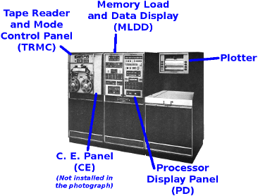
The photo to the left gives you an overview of some of the
portions of the PTC main console used in the emulation. The
Tape Reader and Mode Control Panel, though shown, isn't actually
needed by the emulation, since the software is loaded from
yaLVDC's command line rather than from a tape drive. The
Tape Reader, by the way, accepted a punched tape, not a magnetic
tape. One of the test procedures refers specifically to a
short paper tape, although perhaps longer mylar tapes may have
been used when the PAST program was read.
On the other hand, among the items truly needed by the emulation,
the C. E. Panel apparently hadn't been installed when the
photograph was taken, so our handy caption just points to an empty
space. How the C. E. panel fits into the indicated space in
the PTC cabinet isn't clear to me, but that's life!
Hopefully the photo gives you an idea of the general layout, in
spite of its deficiencies.
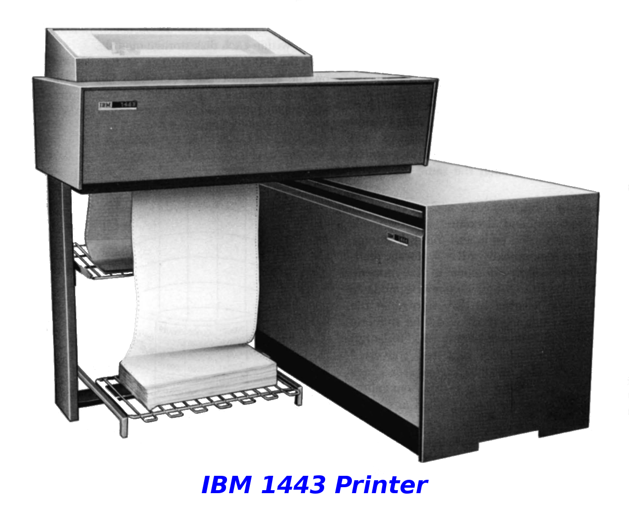
We do know that the printer (photo to the right) was an IBM 1443, and that the plotter was a Calcomp 565.
The PTC's typewriter peripheral isn't depicted in any photos I've
found, nor have I been able to determine its model number.
It printed stuff and had a keyboard, so what more is there to know
about its visual appearance, really? I would hazard a guess
that it was a modified IBM Selectric Typewriter, for whatever an
uninformed guess from me is worth.
To run the test procedures in the PAST program, the principal PTC
interfaces you have to interact with are the three control panels,
which are obviously a bit too small to see in the photo above, so
below you'll find a more-detailed representation of those.
Clicking on any of them should give you enlarged view. Not
everything you see is reproduced in the emulation precisely as-is,
because not all of it is relevant to emulation of the PTC's CPU or
running the PAST program's self-test procedures. For
example, the emulated PTC has no power supplies, so emulating the
Power Control area of the Processor Display Panel (bottom of
far-right image) would be rather pointless.
 |
 |
 |
| Test Procedure # |
Title |
PTC Documentation Figure |
Required Program Load |
Assessment of Utility |
Link to the Corrected Test
Procedure |
Comment |
|---|---|---|---|---|---|---|
| 1 |
Power Checks | 7-2 |
(none) |
Useless; relates to non-emulated hardware. | n/a |
|
| 2 |
Timing Adjustments |
7-3 |
(none) |
Useless; relates to non-emulated hardware. | n/a |
|
| 3 |
Tape Reader Controls and PTC and Printer
Timing Checks |
7-5 |
(none) |
Useless; relates to non-emulated hardware. | n/a |
|
| 4 |
Memory Loader Automatic Checks |
7-6 |
(none) |
Useless; relates to non-emulated hardware. | n/a |
|
| 5 |
Memory Loader Manual Checks | 7-7 |
tape p/n 6001247 PROGRAM=PROC5-7 |
Partially useful. |
Procedure |
We don't actually have a program listing
for the test software from the original tape, or any
documentation for that program. The test program
specified is one that I intend to write myself, though I
have not yet done so. Test procedure #5 seems to work
fine if the program PROC9 is used instead; procedures 6-8,
however, will fail if that is done. |
| 6 |
Data Display Checks | 7-8 |
tape p/n 6001247 PROGRAM=PROC5-7 |
TBD |
TBD |
See the comment above. |
| 7 |
Central Processor Manual Checks | 7-9 |
tape p/n 6001247 PROGRAM=PROC5-7 |
TBD |
TBD |
See the comment above. |
| 8 |
Central Processor Memory Automatic Check | 7-10 |
tape p/n 6001232 PROGRAM=PROC8 |
TBD |
TBD |
See the comment above. |
| 9 |
Self-Test Program Checks | 7-11 | tape p/n 6001236 PROGRAM=PROC9 |
The test procedure is 100% useful. | TBD |
The PROC9 program is essentially
the PAST program. However, there's a handful of steps
in the test procedure that I have simply been unable to
comprehend, after much effort in attempting to do so.
For those few steps, the corresponding lines of code in the
software have been commented out and replaced by an equal
number of instructions which have no effect, thus preserving
memory addresses but bypassing the failing steps. |