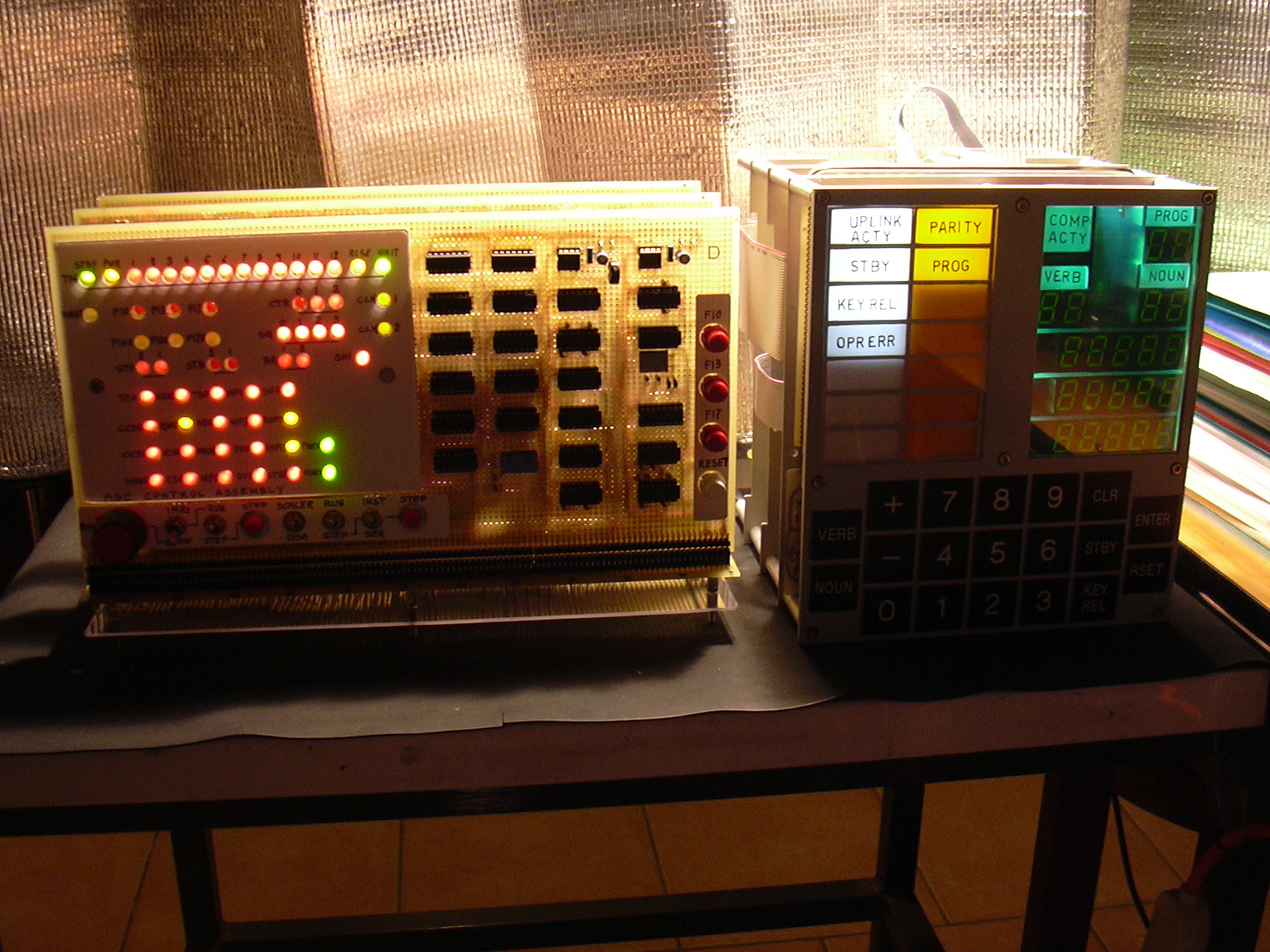
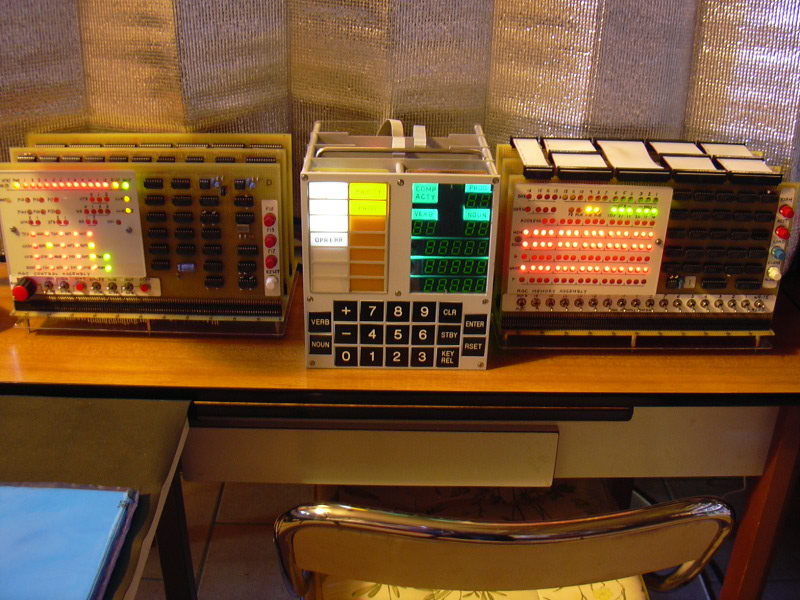
Contents

This page is devoted to physical implementations of the Block I and Block II AGCs, and their peripherals such as DSKYs.  In other words, to physical devices that you could build and keep in your living room to impress friends and neighbors.  Be the first on your block to have one!

John Pultorak's Block I AGC Project

The Pultorak PDFs

John Pultorak and his AGCJohn Pultorak has constructed a physical (not virtual), working model of a Block I AGC out of 74LS-series low-power Schottky TTL devices.  The model works, and runs software which John has adapted from Colossus 249 software.  John's unit even has the same general appearance as the original Block I AGC prototype!  Of course, Colossus 249 software is targeted for the Block II AGC rather than the Block I AGC, but John did not then know of any existing Block I source code, and indeed, even the Colossus 249 software listing he had at the time was only a partial one rather than a complete program.
 
I think I've harped on this point endlessly in the past, but at the risk of beating a dead horse, please don't expect John's schematics to be the actual Block I AGC schematics.  Those simply weren't publicly available when John did his work.  John's work, rather, is a fantastic creation of a workalike, based on his reading of available documentation.  The Block I AGC and DSKY schematics have since become available, though, and if you want those the place to look is on our electro-mechanical page rather than here.  Okay, you've been warned now, whether you wanted a warning about it or not, so feel free to continue reading about John's accomplishment!

No manned mission ever flew with a Block I AGC.  It was originally intended that Apollo 1 and Apollo 2 would be Block I missions; but I'm sure you know what happened to Apollo 1, and Apollo 2 never took place.  The unmanned missions AS-202 (sometimes referred to as Apollo 3, though it took place before Apollo 1 would have), Apollo 4, and Apollo 6 did use Block I AGCs.

John has thoughtfully provided us at Virtual AGC with his schematic diagrams, with adapted Block II software, and with his cross-assembler, all of which are a bit tricky otherwise to get in machine-readable form.  He has also documented his project in what I'll refer to as the Pultorak PDFs, which you may find a lot of other places on the web, but which I provide here as well, since why not?  The following block quote is simply a duplicate of what was on the sort-of-but-not-quite-discontinued klabs website:

Block I Apollo Guidance Computer (AGC):
How to build one in your basement

Material developed and provided by John Pultorak, who is kind enough to put these files into the public domain with no restrictions on their use.

Abstract

This report describes my successful project to build a working reproduction of the 1964 prototype for the Block I Apollo Guidance Computer. The AGC is the flight computer for the Apollo moon landings, with one unit in the command module and one in the LEM.

I built it in my basement. It took me 4 years.

If you like, you can build one too. It will take you less time, and yours will be better than mine.

I documented my project in 9 separate files:

Part 1 - Overview [8.1 MB]: Introduces the project.
Part 2 - CTL Module [9.9 MB]: Design and construction of the control module.
Part 3 - PROC Module [6.7 MB]: Design and construction of the processing (CPU) module.
Part 4 - MEM Module [6.8 MB]: Design and construction of the memory module.
Part 5 - IO Module [7.0 MB]: Design and construction of the diskplay/keyboard (DSKY) module.
Part 6 - Assembler [0.5 MB]: A cross-assembler for AGC software development.
Part 7 - C++ Simulator [5.2 MB]: A low-level simulator that runs assembled AGC code.
Part 8 - Flight Software [2.8 MB]: My translation of portions of the COLOSSUS 249 flight software.
Part 9 - Test & Checkout [0.9 MB]: A suite of test programs in AGC assembly language.

Why build an AGC?

Early computers are interesting. Because they're simple, you can (if you like) actually understand the entire computer, from hardware to software.

The AGC is the most interesting early computer because: it flew the first men to the moon and has interesting architectural features.

How is this Related to Virtual AGC?

It's not.  John's project is not an offshoot of the Virtual AGC project, or vice-versa, and neither project uses materials created by the other.  But John's project is at an end, and he doesn't want the hassle of maintaining a web presence for it, whereas Virtual AGC is an ongoing project.  (But see our Block 1 page.)  So as a courtesy, the Virtual AGC website is going to host supplemental materials for the Pultorak project that haven't worked their way into the other websites mentioned above.

I should mention, though, that it was John who acquired for us all of the documentation and source code that we presently have for the LM's abort computer.  (Of course, I had to write the assembler and simulator myself, so he didn't do everything for us!)  And, the existence of his software Block I simulation (see below), which he wrote in preparation for his hardware simulation, has been extremely helpful in the creation of our own Block I simulator.  So it would be hard to overestimate the value John has had for us a Virtual AGC.  Thanks, John!

The Supplemental Materials

Copyright and Licensing

The Pultorak PDFs do not address the question of copyright for the software or schematics, nor the conditions under which they may be used by others, though the webpages themselves are copyrighted by John.  Obviously, the quote from klabs.or earlier claims that John has put them into the public domain. John has told me that he wants everyone to be able to use the software and hardware freely.  Click here to see an email in which he explains this.  (And just in case you wonder about the context, click here to see email containing my copyright/licensing questions to which he is replying.)

AGC Source Code

AGC source code (flight software adapted for Block I and for John's cross-assembler, test & checkout software, and so forth) is provided in the Pultorak PDFs, but you have to have some means of extracting them to use them for anything.  Moreover, the PDFs often provide assembly listings—i.e., reports generated by the assembler—rather than pure source code.  An assembly listing isn't a legal assembly-language source-code file, so you can't conveniently change and reassemble it.  You can get a zipfile containing the source code and some supplemental files (such as hex files) by clicking here (1 MB). 

Unfortunately, the format accepted by John's cross-assembler isn't compatible with yaYUL (or vice-versa), so these source files cannot be assembled by yaYUL.  They must be assembled using John's cross-assembler.

Assembler and Simulator Source Code

The Visual C++ source code for John's PC-based cross-assembler and simulator do appear in the Pultorak PDFs, but rather than cutting-and-pasting you may find it more convenient to download a zipfile by clicking here (3.7 MB).  In addition to John's original code, there is work in progress on a corrected, cross-platform version of that code for gcc, and on an alternative cross-platform simulator with an unrelated source-code base.

Circuit Design

The Pultorak PDFs do provide schematic diagrams, but some readers have commented that it is difficult to make out some of the details in them.  You can download a zipfile containing the complete CAD files for the design by clicking here (1.7 MB).  The CAD files are in Circuitmaker format (*.ckt), but even if you don't have a copy of Circuitmaker, the zipfile may be worth downloading because it also contains:
At the time John created these materials and first sent them to me, Circuitmaker was available commercially, and if you couldn't afford the full version of the program you could either have downloaded the free but limited "student" version of the software, or else you could download a full but time-limited demo version of the program.  Since that time, however, the company which was selling Circuitmaker has apparently been acquired by Altium, and the Circuitmakerprogram has been discontinued According to Altium's website, the substantially more expensive Altium Designer product is supposed to be able to import existing Circuitmaker schematics.  I have no idea whether this is true or not, though my past experiences in such situations leads me to be suspicious about it.  If anybody else has tried it (and cares to convert John's schematics for me), please let me know.

In order to run Circuitmaker, you have to use Options/LibraryLocation (full or demo version) or File/Preferences/DirectoriesAndFiles (student version) on the menu to set the location of the "user library" (USER.LIB) that comes in our zipfile.  (After doing so, you will probably also have to exit from Circuitmaker and then re-run it, because Circuitmaker will already have loaded the default USER.LIB into its internal cache, and it won't reload it until being restarted.)   Otherwise, when you load the schematics they will have wires but no electrical components on them.  Incidentally, although Circuitmaker2000 is a Windows program, both the student and demo versions run just fine under Linux with CrossOver Office.  They may run fine too under normal Wine, but I haven't tried it.

One thing you will likely want to do with Circuitmaker is to create a netlist.  Neither the student nor demo versions of Circuitmaker seem to want to admit the notion that a single IC can contain multiple gates, and will therefore likely display an error prompt asking if you want to "correct" this condition.  If you say "yes", Circuitmaker will arbitrarily relabel the components within the schematic, so that only one gate appears in each package.  My advice would be to say "no" (not to correct), as the only negative side-effect of doing so appears to be that the netlist file will have duplicate entries for the packages with multiple gates, but the wire-list will be correct.

Integrated Development Environment (IDE)

Donna Polehn has created an GUI IDE (I think, Windows only) based on the Pultorak Simulator and assembler, which you can find at https://github.com/donnaware/AGC.  In order to build it, you need C++Builder 6.  I've not tried it, since I don't personally have C++Builder 6 and don't normally run Windows, but I expect it's interesting.

Donna tells us also that she has made a functional Block I using the Terasic DE0 FPGA development board, as well as a custom FPGA board.  Those are available at the link listed above.


Mike Stewart's Block II AGC Project

You can find all the data on Mike's project at these two GitHub sites:
You have to take what I say about Mike's project with a bit of a grain of salt, because Mike has used his Block II simulator as a weapon for justice, rather than treating it as a work of art, and so I have to give him very high marks just on that basis alone. 

No, wait, is that what I wanted to say?

I jest, of course, but it may not be so far off.  What Mike has done, in his quest to perfect his simulation, has been unique.  He has used his hardware simulator to do detailed comparisons against our own software AGC simulator, yaAGC, and to repair yaAGC when he has found it to be broken in some way, along the way becoming a top contributor to the Virtual AGC project.  The problems he has found have certainly been subtle, but real.  One benefit to Virtual AGC is that bugs preventing yaAGC's use for landing the NASSP/Orbiter LM on the Moon have been fixed, and I got a nice note a few weeks ago (say, in late August of 2016) saying that they had finally landed on the Moon with any program alarms or other problems!  But there has apparently been some help flowing in the opposite direction as well, since Mike tells me that Jim Lawton's AGC wire-lister from our own GitHub repository was essential to his work.  Go figure!  I didn't even know it was there.  Good job, Jim!

As part of this, Mike has also been instrumental in acquiring AURORA, a very early AGC LM program, because it was the last AGC program to contain a full suite of test-suite software, which should help him (and us!) to locate yet other subtle bugs in the simulations, if bugs there be.

Mike's project also stands out because he has used open-source tools, so if you have the time, the expertise, and the will, you can reuse the material from his project without having to acquire proprietary tools to do so.

So while I haven't any fancy exclusive-to-VirtualAGC graphics of Mike's work to present to you here, I can't help but recommend it highly to you!


Steven Hauer's Implementation

Although (see preceding section) I don't have fancy graphics from Mike Stewart's project to show you, Steven Hauer has been busy working on implementing Mike's work, and has sent graphics galore.  Because I am lazy, I'll let Steven describe it for you himself without any of my normal, pesky reinterpretations or editing.

OVERVIEW

Here is a physical implementation currently in progress of Mike Stewart's Block II AGC design.  I started the process of creating this AGC about 20 months ago by researching available AGC design information and implementation examples.  I wanted to create a Block II version of the AGC capable of running the full software.  The idea of creating an AGC that mimics the original Block II circuits also appealed to me greatly, so Mike's design based exclusively on NOR gates, inverters, and open collector drivers was exactly what I was looking for.

I have implemented Mike's design of A01 - A24 plus his version of the fixed/erasable memory board B01 exactly as defined in his KiCad schematics available online.  The only exception is a change in memory devices used on B01 to options available for 5V logic and through-hole design. 

I intend this AGC to demonstrate full functionality so I have brought out the full set of I/O signals and the monitor connector signals.  I use the monitor connector signals for basic integration testing via a monitor breakout board of my own design that also provides interfaces to a logic analyzer.

Instead of the transformer coupled I/O of the original AGC, I applied open collector digital drivers for all outputs added directly to the I/O boards.  For the inputs I used a simple emitter follower for the high speed inputs and the original 'D' circuits for handling the switch inputs.  The simplification of the signal conditioning allowed me to use only 2 interface circuit boards.

My intention is to eventually create a full complement of hardware based simulations of all peripheral devices, uplink/downlink, and a working hardware implementation of the monitor console (also called the core rope simulator) to demonstrate historically accurate monitor functionality.
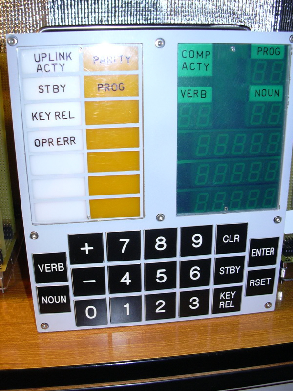
DSKY

The DSKY design is my own.  Instead of multiplexing the display drivers like in John Pultorak's DSKY, I have decided to drive the led segments primarily from open collector driver ICs and each 7-segment display will have its own latching BCD decoder/driver instead of latching relays.  The translation of the AGC digit values to BCD will be accomplished with some old 32x8 bit fused link bipolar PROMS.  Decoding of the AGC OUT1 channel (channel 10 oct) will use a combination of a 4 to 16 decoder and a series of nor-gate based flip flops and gating logic similar to the AGC implementation.

The DSKY push buttons are as close to the orginals as I could find comercially available.  They will be wired identical to the original DSKY and make use of the same diode array for encoding.

There will be 4 PCBs in the DSKY:
- Display board
- Display driver board
- Decode and latch board
- I/O board with signal conditioning and the push button diode array

I currently have the first two boards completed.
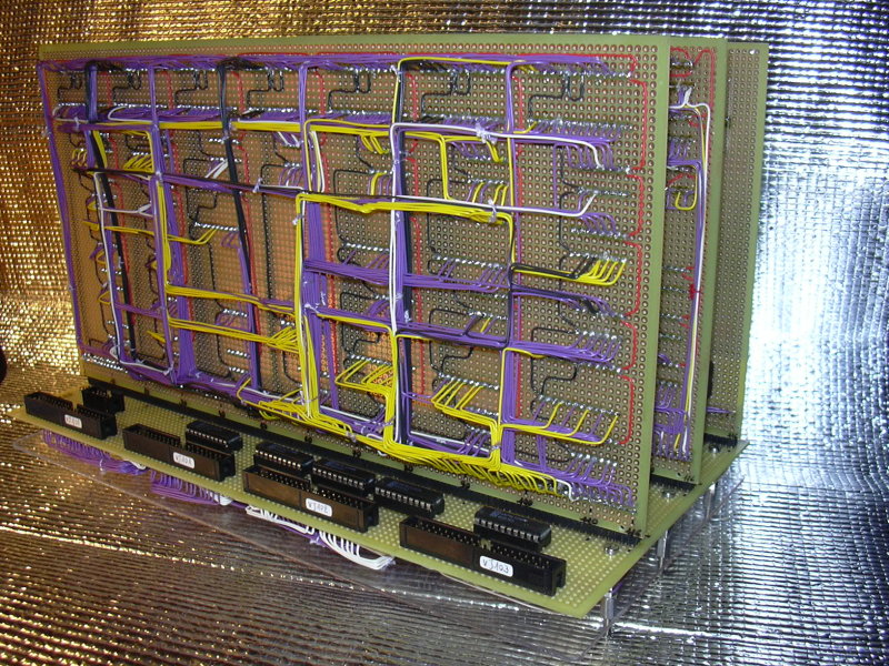
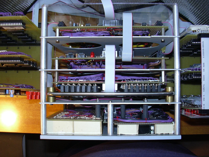
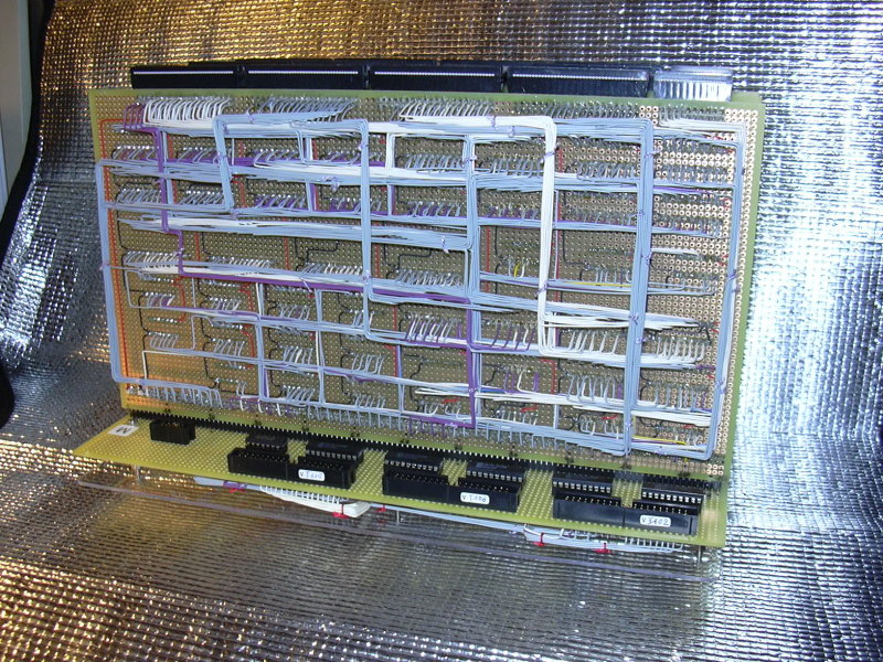
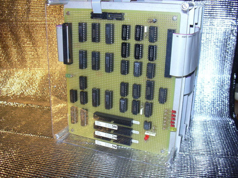
AGC CONSTRUCTION

Each AGC module is fabricated on a 4 layer PCB using 14-pin DIP packages.  I initially thought I would wire-wrap each module but after completing A01 and A02 I quickly determined that wire-wrapping the modules was not a viable option so I went with PCBs.  I used KiCad for all PCB layout to ensure they matched Mike's schematics.

The chassis is made of aluminum plate and angle stock.  The plates for the module connectors and the card guides were ordered online and laser cut.

The backplane is wire-wrapped by hand.  I generated a backplane netlist within KiCad and printed out a hard copy.  Careful use of highlighter markers and triple counting each pin has so far yielded an error free backplane.  The backplane took about 10 months of part time effort (several hundred hours) to complete and I ended up using about 2200 feet of wire.

CURRENT FUNCTIONALITY

Pictures show completed AGC with modules A01 - A24 plus two input conditioning boards.  I've included some logic analyzer screen shots showing the first time I got GOJAM working and also a couple screen shots showing the 4 instructions of the startup entry vector executing from the validate code.  The screen shots showing instruction names are driven from signals via the monitor connector breakout board.

Current computer runs validation program successfully through to completion.  I don't have a DSKY yet so I confirmed successful completion by watching '77' be written to CH10 (oct) for the DSKY signaling the sucessful completion of the program.

I have also loaded Luminary 210 and the program runs without any alarms other than 'NO ATT' which makes sense since there is no IMU (yet).  I can watch PINBALL (the DSKY control routine) clear the DSKY via my logic analyzer and observe some of the interrupt driven idle behavior of Luminary at this point.

FUTURE PLANS

After the DSKY is complete, I plan on creating an interface to allow my physical AGC / DSKY to connect to the Orbiter spaceflight simulator, with the NASSP 8.0 Apollo-mission add-on.  Instead of interfacing this package to yaAGC, I will instead connect it to an adaptor that will take the data stream created for the 'ya' packages and translate the packet data to/from the correct hardware signals to interface with my AGC.

— Steven Hauer, 11/2018
Of course, I know that what you really want to see are the pictures, so here they are.  Click any of them to see an enlarged view:


A01 - A07 + A13

A01 - A15 + B01

A05

Backplane 1

Backplane 2

Backplane 3

Chassis 1

Chassis 2

Monitor Board 1

Monitor Board 2

Running with Monitor Board

GOJAM Control Signals

Start Vector 1

Start Vector 2
Click to enlarge
DSKY Button Wiring
Click to enlarge
DSKY Display 1
Click to enlarge
DSKY Display 2
Click to enlarge
DSKY Display Test


Dario Kubler's Apollo 16 AGC/DSKY Simulation Project

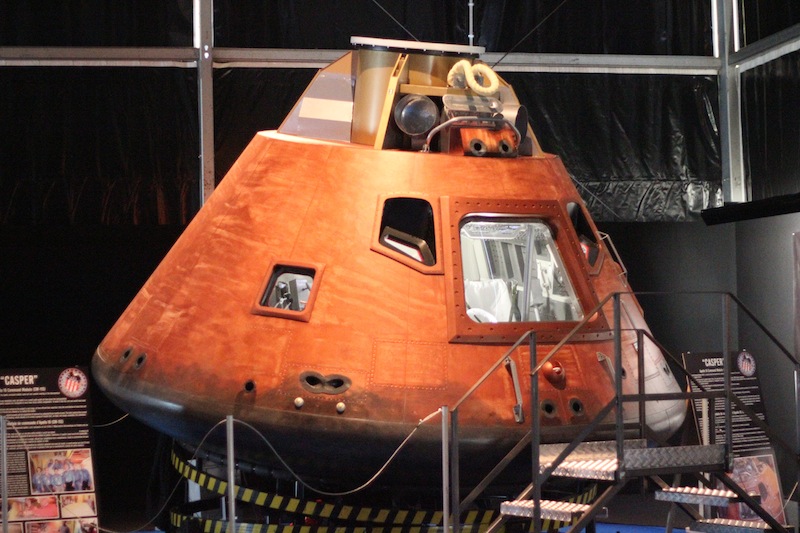
Dario was part of a team (largely people from the Fondazione Osservatorio Astronomico M13) that created a 1:1 scale mockup of the Apollo 16 Command Module ("Casper") for 2012 exhibition called Esplorando, in Varese, Italy, near Milan.  Dario's part of the task was to create a working DSKY, which would be interfaced via bluetooth to a PC running the Artemis AGC program in our yaAGC AGC simulator software.  Of course, yaAGC has no direct bluetooth support, but Dario wrote a C++ program that interfaced between yaAGC and bluetooth. 

Apparently, the exhibition went very well.  Charlie Duke, the LMP for Apollo 16, was one of the visitors.  I'm told that he entered the capsule, played with the AGC/DSKY combo, said that it was very realistic, and passed his compliments to us.  So ... thanks, Dario!

Actually, there's a YouTube video, with Charlie Duke, of the Casper mockup's unveiling ceremony:


After Esplorando, the capsule was moved to the flight museum located in the Malpensa International Airport, in Milan.

Here's a YouTube link to a short video of Dario's AGC/DSKY combo in operation:


Since then, Dario has managed to port yaAGC into an embedded system, based on the PIC32-MZ (a 32-bit MIPS-based MCU), with 2MB of flash memory and 512KB of RAM, using the XC32 gcc-based compiler.  Dario himself works at Microchip (the manufacturer) himself, so that seems like a natural progression.


Dimitris Vitoris's Block I and Block II AGC Project

The project of Dimitris ("Jim") Vitoris takes over where John Pultorak's project stops.  The project is still in its very first stages, so please don't take any statements made here as commitments!  But the basic idea of the project is to be able to create a physical implementation of a Block II AGC and DSKY, which (unlike John Pultorak's Block I AGC above) can be constructed by hobbyists, without requiring the immense skill needed to construct a Pultorak AGC.

Here is a very uncertain roadmap of the project.  It may be that all of these phases will be completed, or it may be that the project will stop where it is now.  Or perhaps some phases might be skipped.  There is no timetable.  But however it goes, thanks Dimitris!

Project Phase
Description
Status
A0
Conversion of John Pultorak's Block I AGC design (schematics only!) to Eagle CAD, with corrections and small improvements.
Ready now!
A1
A clean restructuring of the Block I design -- for example, with AGC, DSKY, and monitoring busses separated into independent assemblies rather than being a part of one large assembly.
Preliminary data available.  (See change log.)
B0
Block II AGC design (schematics and printed-circuit board layout!) using 74xxx TTL logic.
Possible
B1
Size reduction of Block II design, using surface-mount parts and FPGAs.
Possible
C0
Further, final size reduction of the Block II design, with added Virtual AGC compatibility.  (This would mean, for example, that one of Dimitris's physical DSKY could be used with a PC running Virtual AGC.)
Possible

Download 20090927 snapshot now!

The download is a zipfile containing the complete set of materials that have been created by Dimitris so far.

Dimitris uses Eagle CAD for this project (www.cadsoft.de).  Eagle is a cross-platform program that is available for Linux, Windows, and Mac OS X.  While Eagle is a proprietary program that costs money to purchase, there is a free version that can be used with small designs.  I have verified that the free version does allow viewing of the phase A0 schematics on Linux.  Unfortunately, although the purely open-source KiCad CAD software purports to (and probably does, for all I know) import Eagle CAD projects and schematics, I have found that KiCad 6 will not import these files.

Once phase B0 and beyond are reached, it would be valuable to have mechanical design and drawings of things such as DSKYs, enclosures, front panels, and so forth, so that complete physical units can be constructed.  Any mechanical engineers who are interested should contact me at the email address at the bottom of this page.  Mechanical design of a Block II DSKY in particular would be useful, regardless of the how far Dimitris cares to advance his project.

Dimitris has also sent some photos of the physical device he is constructing:


The physical faceplate, work in progress!

Cleaned-up stylized drawing
from which measurements can
be taken.  A CorelDraw file is also
available.

Dimitris mentions that his best estimate of the faceplate dimensions is 18.9 cm (7.44 in.) wide and 21.8 cm. (8.58 in.) high, and points out that additional dimensions can be extract from the right-hand drawing above.

Incidentally, Dimitris owns various bits and pieces of Block I equipment, and here are some photos he was kind enough to send us.  (

Block I AGC logic module
Block I AGC Logic Module

Block I AGC rope-memory module
Block I AGC Rope Memory Module

Block I DSKY power
                        supply
Block I DSKY power
                        supply
Block I DSKY Power Supply


Philip Schmidt's Block I AGC Project

Philip Schmidt has also been kind enough to let us know about his Block I physical implementation.  You can see his write-up of what he's been doing at his own web-page.  Phil tells me that he will eventually provide all of the CAD files for his design (in Altium Designer format), but for right now it's all PDFs while it's a work in progress.


Juan Jose's Block I AGC Project, Running SOLARIUM

Juan Jose has built a Block I AGC-plus-DSKY simulator using a Spartan3 (a Xilinx FPGA) board.  I don't have too many details about how he did it, though he was kind enough to send our mailing list some nice photos of some of the proto-boards he had added to the basic Spartan3 board.

There are also some cute YouTube videos of it in action.  Here is his "Block I Flyby" video — the "flyby" being of his contraption, and not of anything in space:


You can find more by looking at his YouTube user, which is "agcfanatic", but here are a few direct links:

Dave Roberts's Block II AGC Project

Dave Roberts made a physical simulation of a Block II AGC, written in VHDL for a Xilinx Spartan-3E FPGA.  His code can be found here.  It was apparently, at least partially, intended to work with Tony David's physical DSKY, about which I know nothing.

Unfortunately, Dave was having some problems with his hardware Block II simulator at the time of the last commit (in 2012) of his source code as listed above, particularly in regard to the DV instruction. He apparently later fixed this DV problem, but the fix never migrated online.  In point of fact, at that time yaAGC (which of course, Dave does not use) also had a number of problems with the implementation of the DV instruction, later fixed by Mike Stewart, and some of Dave's problem may have related to the Validation Suite of AGC code we provide having been in error due to this.

Who's Building Them?

Alessandro Cinquemani

Of course, the great thing about these projects is that you can start from them and build your own AGC or DSKY.  If you have done so, feel free to send me some photos and/or descriptions of what you've built.  Where is Heathkit when you need it?

Alessandro Cinquemani of Aviano, Italy, has sent in the very nifty photo (click to enlarge) seen below.

Click to enlarge.

As I understand it, here we're seeing the DSKY and CTL modules, which Alessandro built by following through on John Pultorak's documentation.  Alessandro is still working on the MEM and PROC modules, but when the AGC is fully operational is considering making actual circuit boards.  Great job, Alessandro!

Alessandro has sent us a whole gallery of photo updates, reluctantly down-sampled by me to save some space.  He tells us (2009-06-17) that he thinks he may be able to finish it up in 3-4 months.  Click'n'enjoy:


Bruno Muller

Bruno Muller has created a physical DSKY that interacts with yaAGC via the NASSP plug-in for the Orbiter spacecraft simulator.  He has made a video and sent me the following charming YouTube link:


Other?

My personal bias is that I'd prefer it if these materials were available for use with a free and open-source CAD system rather than proprietary systems such as Circuitmaker and Eagle.   The subsequent discontinuation of the Circuitmaker program (mentioned above) puts the problem in stark relief:  John Pultorak spent a lot of time creating these materials, and yet within just a few years nobody will be able even to open the CAD files he created.  This website deals with things that happened (as of this writing) 40 years ago, and I'd like the  information presented here to still be useful 40 years from now ... or 400.  But the CAD files have proven to have a shelf-life of less than 5!

Such absurd situations should come as no surprise to anybody with substantial experience in using electrical CAD systems.  Speaking from experience, every proprietary electrical CAD program is eventually discontinued either by virtue of acquisition of the manufacturer or else a strategic decision by the manufacturer, and the schematic format is then orphaned, usually even without any documentation.  Yet I've never encountered an electrical designer who had noticed this fact or believed it was a problem; instead, CAD software is invariably chosen on the basis of whatever features are most convenient to the designer at that moment in time.   Indeed, I've made such selections myself, based on whatever software has the fastest or best autorouter.  But the autorouter relates only to PCB layout, and has essentially no relation to schematic capture, which could be done by a separate program from the PCB layout program entirely. Schematic capture and PCB layout are interrelated only by exchange of netlists and back-annotation info, and the notion that the two must be integrated into one program is a fantasy promoted by CAD manufacturers and swallowed en masse by circuit designers.  I'd venture the advice that if you're going to use a proprietary CAD program, it's best to use one that supports the Orcad file format, and to archive your work in that format, since it's the closest thing to a de facto standard that exists at the present time.

It would be nice if an open-source CAD tools were used instead, so that the schematics, PCB layouts, etc., would be freely editable by everybody without purchasing a proprietary tool.  If anybody wants to convert the CAD files into a more open format, your help would be welcomed.  Among those who think the way I do, the open-source KiCad tool seems to have currently captured the most mind-share, and if all the cool kids are using it, you may as well too!  Of course, if you absolutely insisted, we'd be happy to have Orcad, or any other format as well!  I've so far not found an automated tool to perform the conversion of Circuitmaker or Eagle to any other format.  (If you wanted to write a program that converted Circuitmaker or Eagle files to  some open format, I'm sure that would be even more valuable than the conversion itself.)


This page is available under the Creative Commons No Rights Reserved License
Last modified by Ronald Burkey on 2019-01-21.

Virtual AGC is hosted
              by ibiblio.org